Facilities
University of Virginia Supersonic Combustion Facility
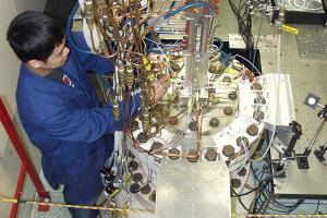
The University of Virginia Supersonic Combustion Facility is an electrically-heated supersonic wind tunnel that is capable of simulating a hypersonic vehicle flying at five times the speed of sound. The facility is used in research that is aiding the development of scramjet engines that one day could propel aircraft at speeds of up to 15 times the speed of sound. These engines could also be used to make space access cheaper and safer.
The facility has a continuous flow capability that allows unlimited duration testing. During combustion testing, flow speeds of 2,200 mph are generated with flow temperatures approaching 4000° F. Including warm up and warm down periods, tests are usually conducted over a 5 to 6 hour period with steady state test conditions typically held for 1 to 2 hours. Since the facility is electrically heated, it does not have a freestream that is vitiated with combustion heater products. However, the major combustion species of water and carbon dioxide can be added to the freestream. Therefore, the clean air of flight or a vitiated combustion heater test medium can be simulated. Optical access to the combustor test section permits highly accurate, non-intrusive flow measurements in the high-speed combusting flows. Laser-based techniques applied to these complex reacting flows provide information to enable an understanding of the underlying physics of high-speed combustion and for the development of databases for the validation of advanced numerical computer models. In house diagnostics include Stereoscopic Particle Image Velocimetry (10 – 1000 Hz), Tunable Diode Laser Absorption Spectroscopy (TDLAS) tomography and high speed (MHz) Schlieren and shadowgraph flow visualization.
Variable Mach Number Supersonic Wind Tunnel
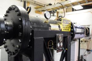
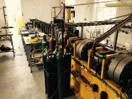
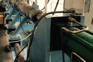
The Variable Mach Number Supersonic Wind Tunnel is capable of providing a test flow with a continuously variable Mach number in the range of 1.3 to 3.1. The facility (see left image) consists of a 300 psi compressed air source, settling chamber, variable nozzle block (see right image detail), test section, and diffuser. Formally a pilot facility for the NASA Langley Supersonic Unitary Plan Wind Tunnel, the facility is used to study supersonic aerodynamics and compressible flow phenomena. It has been used in the past to simulate fuel-air mixing downstream of a pair of swept ramp fuel injectors. The test time of the facility is typically 2.5 minutes and it has a test section cross section of 3 × 3 inches. The facility is equipped with low frequency pressure measurement and shadowgraph flow visualization systems. The wind tunnel is used for both research and undergraduate instructional laboratories.
Hypersonic Aerodynamics Wind Tunnel
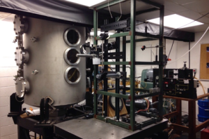
This unique hypersonic wind tunnel at the Aerospace Research Laboratory is used to produce speeds to Mach 16 continuously. The facility consists of a large vacuum tank into which nitrogen is introduced through a sonic orifice. The large pressure ratio across the orifice produces an underexpanded jet. Models are placed along the centerline of the jet for testing from Mach 1 to 16. NASA funded research has been done related to spacecraft entering the Martian atmosphere using retropropulsion rockets and reaction control jets. Current testing employs a model consisting of an array of Mach 5 jets impinging on a flat plate to simulate the impact of spacecraft retrorockets on the surface of the International Space Station (ISS). Such impacts have been observed during docking maneuvers, causing damage to the ISS solar panels.
Measurements are made in the flow field around these models using a nonintrusive optical technique called Planar Laser-Induced Iodine Fluorescence (PLIF). This technique can measure all thermodynamic parameters as well as velocity. It is the only technique capable of such quantitative, spatially resolved measurements in these highly rarefied flow fields.
Inertial Particle Separation Wind Tunnel
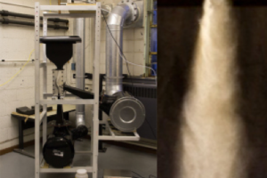
The Inertial Particle Separator (IPS) Wind Tunnel is a two-dimensionally simplified test facility that approximates the particle filtration systems found on helicopter jet engines. The wind tunnel (on the left in the image) employs a pull-down configuration whereby the flow enters a contraction section followed by the test section with optical access covering a length of 30 cm and spanwise width of 20 cm. The inlet section is capable of flow inlet speeds of up to 150 m/s and separates the incoming flow into two legs: a scavenge flow (up to 300 SCFM) and a core flow (up to 1500 SCFM). The two flow legs are independently controlled with a PID automated controller. These flow conditions simulate realistic full-scale engine inlet conditions in terms of flow velocity, length scales, and test particles, which are released above the contraction section as a dilute particle-laden jet (right). A variety of separator geometries can be tested and the available diagnostics for this facility allow particle separation efficiency measurements as well as velocity field descriptions using Particle Image Velocimetry (PIV) and flow visualization using High-Speed Video (20,000 fps) data capture.
ASOS Shock Tunnel
The ASOS Shock Tube installation is a large scale shock tube facility with a test section cross sectional area of 200 × 200 mm. This test section is specially engineered to withstand the dynamic loadings at the facility-design envelope with a fully transparent (polycarbonate) construction. The shock tube is supported in a horizontal orientation and employs a double-diaphragm bursting arrangement for controlled operation. Shock Mach numbers up to 3.5 and a flow dynamic pressure of 2 MPa can be generated. The 2 m long driver section ensures that uniform flow conditions exist over a time period of 3 to 8 ms.
The simultaneous use of three high-speed cameras provides a unique opportunity to observe the reaction of the target to the shock using different points of view with frame rates up to 100 MHz. Application of different visualizing techniques allows one to observe the reaction using different methods (photography, shadowgraphy) and to measure density gradient distributions during the process (Schlieren visualization).
PISTL Shock Tunnel
The PISTL facility is a shock heated wind tunnel that is capable of operating in both shock tube mode and expansion tube mode. Formerly a federally owned facility located at NASA Langley Research Center, the wind tunnel is being installed and recommissioned at the ARL. The facility is approximately 50 feet long and has an internal diameter of 3.5 inches. It can generate flow velocities exceeding 4000 m/s, (close to 9000 mph), and is therefore well suited to research on the aerodynamics associated with hypervelocity flight, including atmospheric re-entry of a spacecraft and the entry of a spacecraft into the atmospheres of other planets in the solar system. It is also capable of high Mach number, high enthalpy boundary layer experiments and supersonic combustion experiments. The research applications of this facility go beyond hypersonic aerodynamics and combustion to include chemical kinetics, plasmas, and blast wave damage and mitigation, as well as diagnostics and measurement technique development. The facility complements the ASOS shock tube facility at ARL due to the higher flow velocities and enthalpies that can be generated. The facility is being installed with an array of high frequency (MHz) pressure transducers as well as a state-of-the-art, high-speed (MHz) digital data acquisition system. High speed (MHz) Schlieren and shadowgraph flow visualization are also available.
Diagnostics Capabilities
Pressure sensors
- 10 Hz measurements: pressure taps connected to a Netscanner™ pressure scanner (80 channels)
- MHz measurements: Kulite pressure transducers
Temperature sensors
- 10 Hz measurements: surface and bore thermocouples connected to a NetScanner™ thermocouple unit
PIV is a 2D or 3D non-intrusive velocimetry technique based on the visualization of particles tracking the flow. Their displacement between time-resolved images provides velocity vectors at high spatial and temporal resolution. A laser sheet is used to illuminate a thin section of the flow. All systems below have a stereo-PIV (SPIV) capability.
Lasers
- 10 Hz system: Spectra Physics PIV-400 (type Nd:YAG @ 532 nm, 400 mJ/pulse, 10 Hz repetition rate)
- 1-3 kHz system: Photonics DM50-527DH (type Nd:YLF @ 527 nm, 55 mJ/pulse, 5 kHz repetition rate)
Cameras
- 10 Hz system: 2x LaVision Imager Pro X 2M cameras (2 MPix, CCD, 14 Hz)
- 1-3 kHz system: 2x Photron SA 1.1 (1 MPix, CMOS, 2.7 kHz)
Particles
- Al2O3
- TiO2
- SiO2
- GRAPHITE PARTICLES
Software
- LaVision DaVis 8
- Includes FlowMaster and SPIV extensions
Planar Laser Induced Fluorescence
Finite Element Analysis
In-house shadowgraph and schlieren capabilities
Tunable Diode Laser Absorption Tomography
History of collaborative work with academic and government laboratories to apply advanced experimental diagnostics to UVaSCF (e.g. CARS, PLIF, focused Schlieren, TDLAS) as well as CFD (RANS, LES, DNS)