LSL Simulated Engine Materials Testing Facility
Gas turbine engines provide propulsion for aircraft, ships, and some ground vehicles and are widely used for electric power generation. The materials and coatings used in these engines are undergoing rapid development to increase engine fuel efficiency. As future engine gas temperatures rise towards 1800°C, a variety of facilities have been developed to allow experimental investigation of pairs of the three main variables (stress, temperature, and environment). Due to the high-temperature capability of SiC/SiC Ceramic Matrix Composites (CMCs) compared to conventional superalloys, this material has become the lead candidate material for next-generation gas turbine engines. However, SiC-based CMCs oxidize at high temperature and form a solid silica thermally-grown oxide (TGO) layer. This subsequently reacts with water vapor present in the high-temperature combustion environment and is converted to a gaseous silicon hydroxide. To prevent this erosion of the SiC, environmental barrier coatings (EBCs) must be applied to CMC engine components.
Laser, Steam and Load (LSL) Simulated Engine Materials Testing facility allows the study of the synergistic interactions of all three variables (stress, temperature, and environment) in a manner consistent with fundamental scientific research. This is the nation’s only laboratory-scale testing facility that controllably simulates the mechanical loads, the spatial/temporal temperature gradients, and the chemical environment present in gas turbine engines. This facility enables investigation of the mechanisms by which materials in engines are degraded by environmental attack from water vapor and oxygen-containing combustion gases at temperatures up to 1800°C and pressures up to 12 atm in the presence of static and cyclic mechanical stresses that can exceed 300 MPa. Figure 1 shows the schematics of the test setup.
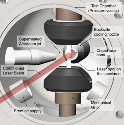
Figure 1: Schematics of the test setup
Table 1 shows the test conditions achievable by the LSL facility in comparison to a gas turbine engine. Figure 2 shows the dimensions of the standard LSL test specimen.
Table 1: Simulated Test Conditions
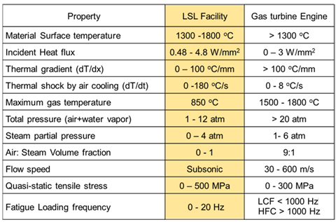
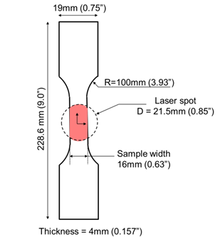
Figure 2: Standard Test Specimen Geometry
Photographs of the facility are shown in Figure 3-5.
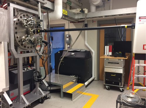
Figure 3: Test chamber and Laser
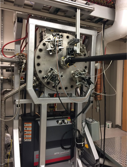
Figure 4: Test chamber
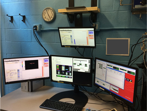
Figure 5: User Control Station
LSL Hourly Rates
If you are interested in using this test facility to test materials and coatings please contact Dr. Wadley at hnw4z@virginia.edu.